- 您现在的位置:买卖IC网 > Sheet目录3873 > PIC18F45K20-I/MV (Microchip Technology)MCU 32KB FLASH 1536B RAM 40-UQFN
2010
Micr
ochip
T
e
ch
nol
ogy
I
n
c.
DS4
1303G
-page
13
PIC18F2XK20/4XK20
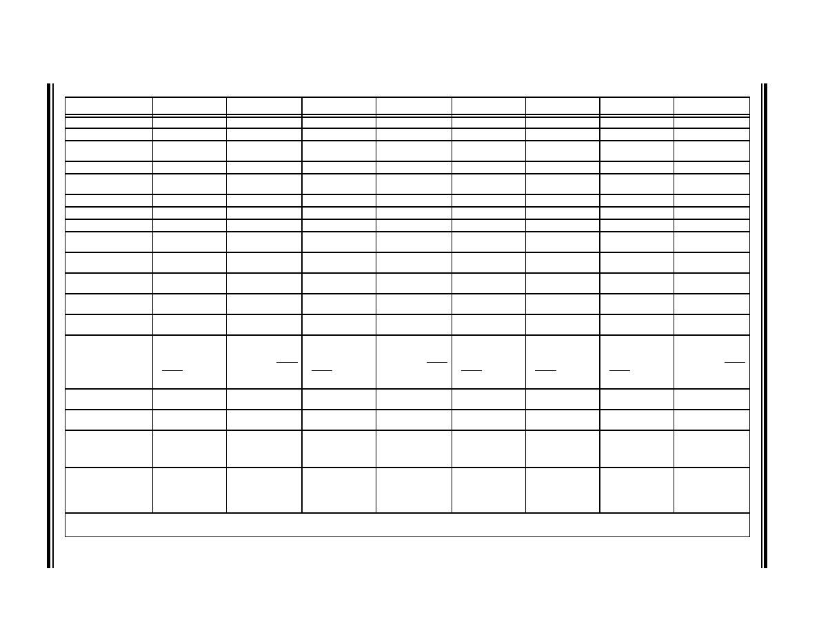
TABLE 1-1:
DEVICE FEATURES
Features
PIC18F23K20
PIC18F24K20
PIC18F25K20
PIC18F26K20
PIC18F43K20
PIC18F44K20
PIC18F45K20
PIC18F46K20
Operating Frequency(2)
DC – 64 MHz
Program Memory (Bytes)
8192
16384
32768
65536
8192
16384
32768
65536
Program Memory
(Instructions)
4096
8192
16384
32768
4096
8192
16384
32768
Data Memory (Bytes)
512
768
1536
3936
512
768
1536
3936
Data EEPROM Memory
(Bytes)
256
1024
256
1024
Interrupt Sources
19
20
I/O Ports
A, B, C, (E)(1)
A, B, C, D, E
Timers
4
44
Capture/Compare/PWM
Modules
111
1
Enhanced Capture/
Compare/PWM Modules
1
11
Serial Communications
MSSP, Enhanced
USART
MSSP, Enhanced
USART
MSSP, Enhanced
USART
MSSP, Enhanced
USART
MSSP, Enhanced
USART
MSSP, Enhanced
USART
MSSP, Enhanced
USART
MSSP, Enhanced
USART
Parallel Communica-
tions (PSP)
No
Yes
10-bit Analog-to-Digital
Module
1 internal plus 10
Input Channels
1 internal plus 10
Input Channels
1 internal plus 10
Input Channels
1 internal plus 10
Input Channels
1 internal plus 13
Input Channels
1 internal plus 13
Input Channels
1 internal plus 13
Input Channels
1 internal plus 13
Input Channels
Resets (and Delays)
POR, BOR, RESET
Instruction, Stack
Full, Stack Underflow
(PWRT, OST),
MCLR (optional),
WDT
POR, BOR, RESET
Instruction, Stack
Full, Stack Underflow
(PWRT, OST), MCLR
(optional), WDT
POR, BOR, RESET
Instruction, Stack
Full, Stack Underflow
(PWRT, OST),
MCLR (optional),
WDT
POR, BOR, RESET
Instruction, Stack
Full, Stack Underflow
(PWRT, OST), MCLR
(optional), WDT
POR, BOR, RESET
Instruction, Stack
Full, Stack Underflow
(PWRT, OST),
MCLR (optional),
WDT
POR, BOR, RESET
Instruction, Stack
Full, Stack Underflow
(PWRT, OST),
MCLR (optional),
WDT
POR, BOR, RESET
Instruction, Stack
Full, Stack Underflow
(PWRT, OST),
MCLR (optional),
WDT
POR, BOR, RESET
Instruction, Stack
Full, Stack Underflow
(PWRT, OST), MCLR
(optional), WDT
Programmable High/
Low-Voltage Detect
Yes
Programmable Brown-
out Reset
Yes
Instruction Set
75 Instructions; 83
with Extended
Instruction Set
enabled
75 Instructions; 83
with Extended
Instruction Set
enabled
75 Instructions; 83
with Extended
Instruction Set
enabled
75 Instructions; 83
with Extended
Instruction Set
enabled
75 Instructions; 83
with Extended
Instruction Set
enabled
75 Instructions; 83
with Extended
Instruction Set
enabled
75 Instructions; 83
with Extended
Instruction Set
enabled
75 Instructions; 83
with Extended
Instruction Set
enabled
Packages
28-pin PDIP
28-pin SOIC
28-pin QFN
28-pin SSOP
28-pin UQFN
28-pin PDIP
28-pin SOIC
28-pin QFN
28-pin SSOP
28-pin PDIP
28-pin SOIC
28-pin QFN
28-pin SSOP
28-pin PDIP
28-pin SOIC
28-pin QFN
28-pin SSOP
40-pin PDIP
44-pin QFN
44-pin TQFP
40-pin PDIP
44-pin QFN
44-pin TQFP
40-pin PDIP
44-pin QFN
44-pin TQFP
40-pin PDIP
44-pin QFN
44-pin TQFP
Note
1:
PORTE contains the single RE3 read-only bit. The LATE and TRISE registers are not implemented.
2:
Frequency range shown applies to industrial range devices only. Maximum frequency for extended range devices is 48 MHz.
发布紧急采购,3分钟左右您将得到回复。
相关PDF资料
PIC16CR76T-I/SS
IC PIC MCU 8KX14 28SSOP
PIC18F13K50-I/P
IC PIC MCU FLASH 4KX16 20-PDIP
PIC16CR76T-I/SO
IC PIC MCU 8KX14 28SOIC
PIC18LF24K22-I/MV
IC PIC MCU 16KB FLASH 28UQFN
PIC18LF24K22-I/ML
IC PIC MCU 16KB FLASH 28QFN
PIC16CR76T-I/ML
IC PIC MCU 8KX14 28QFN
PIC16F627-04/P
IC MCU FLASH 1KX14 COMP 18DIP
PIC18F45J10-I/ML
IC PIC MCU FLASH 16KX16 44QFN
相关代理商/技术参数
PIC18F45K20-I/P
功能描述:8位微控制器 -MCU 32KB Flash 1536B RAM 25 I/O 8B RoHS:否 制造商:Silicon Labs 核心:8051 处理器系列:C8051F39x 数据总线宽度:8 bit 最大时钟频率:50 MHz 程序存储器大小:16 KB 数据 RAM 大小:1 KB 片上 ADC:Yes 工作电源电压:1.8 V to 3.6 V 工作温度范围:- 40 C to + 105 C 封装 / 箱体:QFN-20 安装风格:SMD/SMT
PIC18F45K20-I/PT
功能描述:8位微控制器 -MCU 32KB Flash 1536B RAM 25 I/O 8B RoHS:否 制造商:Silicon Labs 核心:8051 处理器系列:C8051F39x 数据总线宽度:8 bit 最大时钟频率:50 MHz 程序存储器大小:16 KB 数据 RAM 大小:1 KB 片上 ADC:Yes 工作电源电压:1.8 V to 3.6 V 工作温度范围:- 40 C to + 105 C 封装 / 箱体:QFN-20 安装风格:SMD/SMT
PIC18F45K20T-I/ML
功能描述:8位微控制器 -MCU 32KB Flash 1536B RAM 25 I/O 8B RoHS:否 制造商:Silicon Labs 核心:8051 处理器系列:C8051F39x 数据总线宽度:8 bit 最大时钟频率:50 MHz 程序存储器大小:16 KB 数据 RAM 大小:1 KB 片上 ADC:Yes 工作电源电压:1.8 V to 3.6 V 工作温度范围:- 40 C to + 105 C 封装 / 箱体:QFN-20 安装风格:SMD/SMT
PIC18F45K20T-I/MLV01
制造商:Microchip Technology Inc 功能描述:
PIC18F45K20T-I/MV
功能描述:8位微控制器 -MCU 32KB FL 1536b RAM 8b Familynanowatt XLP
RoHS:否 制造商:Silicon Labs 核心:8051 处理器系列:C8051F39x 数据总线宽度:8 bit 最大时钟频率:50 MHz 程序存储器大小:16 KB 数据 RAM 大小:1 KB 片上 ADC:Yes 工作电源电压:1.8 V to 3.6 V 工作温度范围:- 40 C to + 105 C 封装 / 箱体:QFN-20 安装风格:SMD/SMT
PIC18F45K20T-I/PT
功能描述:8位微控制器 -MCU 32KB Flash 1536B RAM 25 I/O 8B RoHS:否 制造商:Silicon Labs 核心:8051 处理器系列:C8051F39x 数据总线宽度:8 bit 最大时钟频率:50 MHz 程序存储器大小:16 KB 数据 RAM 大小:1 KB 片上 ADC:Yes 工作电源电压:1.8 V to 3.6 V 工作温度范围:- 40 C to + 105 C 封装 / 箱体:QFN-20 安装风格:SMD/SMT
PIC18F45K22-E/ML
功能描述:8位微控制器 -MCU 32KB Flash 1536B RAM 8B nanoWatt RoHS:否 制造商:Silicon Labs 核心:8051 处理器系列:C8051F39x 数据总线宽度:8 bit 最大时钟频率:50 MHz 程序存储器大小:16 KB 数据 RAM 大小:1 KB 片上 ADC:Yes 工作电源电压:1.8 V to 3.6 V 工作温度范围:- 40 C to + 105 C 封装 / 箱体:QFN-20 安装风格:SMD/SMT
PIC18F45K22-E/MV
功能描述:8位微控制器 -MCU 32KB 1536b RAM 8bit familynanoWatt XLP RoHS:否 制造商:Silicon Labs 核心:8051 处理器系列:C8051F39x 数据总线宽度:8 bit 最大时钟频率:50 MHz 程序存储器大小:16 KB 数据 RAM 大小:1 KB 片上 ADC:Yes 工作电源电压:1.8 V to 3.6 V 工作温度范围:- 40 C to + 105 C 封装 / 箱体:QFN-20 安装风格:SMD/SMT